- 您现在的位置:买卖IC网 > Sheet目录134 > M1MA174T1G (ON Semiconductor)DIODE SW SS 200MA 100V SOT-323
�  �
�
� � �  �
�
� � �  �
�
� � � M1MA174T1�
� � http://onsemi.com�
� � 4�
� � STEP 1�
� � PREHEAT�
� � ZONE 1�
� � �
� � STEP 2�
� � VENT�
� � �
� � ZONES 2 & 5�
� � STEP 3�
� � HEATING�
� � �
� � STEP 4�
� � HEATING�
� � ZONES 3 & 6�
� � ZONES 4 & 7�
� � �
� � STEP 5�
� � HEATING�
� � �
� � STEP 6�
� � STEP 7�
� � VENT�
� � COOLING�
� � 200°C�
� � 150°C�
� � 100°C�
� � 50°C�
� � TIME (3 TO 7 MINUTES TOTAL)�
� � TMAX�
� � SOLDER IS LIQUID FOR�
� � 40 TO 80 SECONDS�
� � (DEPENDING ON�
� � MASS OF ASSEMBLY)�
� � 205°�
� � TO 219�
� � °C�
� � PEAK AT�
� � SOLDER JOINT�
� � DESIRED CURVE FOR LOW�
� � MASS ASSEMBLIES�
� � 100°C�
� � 150°C�
� � 160°C�
� � 140°C�
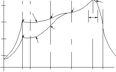
� � Figure 5. Typical Solder Heating Profile�
� � DESIRED CURVE FOR HIGH�
� � MASS ASSEMBLIES�
� � 170°C�
� � For any given circuit board, there will be a group of�
� � control settings that will give the desired heat pattern. The�
� � operator must set temperatures for several heating zones,�
� � and a figure for belt speed. Taken together, these control�
� � settings make up a heating aprofileo for that particular�
� � circuit board. On machines controlled by a computer, the�
� � computer remembers these profiles from one operating�
� � session to the next. Figure 7 shows a typical heating profile�
� � for use when soldering a surface mount device to a printed�
� � circuit board. This profile will vary among soldering�
� � systems but it is a good starting point. Factors that can�
� � affect the profile include the type of soldering system in�
� � use, density and types of components on the board, type of�
� � solder used, and the type of board or substrate material�
� � being used. This profile shows temperature versus time.�
� � SOLDER STENCIL GUIDELINES�
� � Prior to placing surface mount components onto a printed�
� � circuit board, solder paste must be applied to the pads. A�
� � solder stencil is required to screen the optimum amount of�
� � solder paste onto the footprint. The stencil is made of brass�
� � or stainless steel with a typical thickness of 0.008 inches.�
� � The stencil opening size for the surface mounted package�
� � should be the same as the pad size on the printed circuit�
� � board, i.e., a 1:1 registration.�
� � TYPICAL SOLDER HEATING PROFILE�
� � The line on the graph shows the actual temperature that�
� � might be experienced on the surface of a test board at or�
� � near a central solder joint. The two profiles are based on a�
� � high density and a low density board. The Vitronics�
� � SMD310 convection/infrared reflow soldering system was�
� � used to generate this profile. The type of solder used was�
� � 62/36/2 Tin Lead Silver with a melting point between�
� � 177±189°C. When this type of furnace is used for solder�
� � reflow work, the circuit boards and solder joints tend to�
� � heat first. The components on the board are then heated by�
� � conduction. The circuit board, because it has a large surface�
� � area, absorbs the thermal energy more efficiently, then�
� � distributes this energy to the components. Because of this�
� � effect, the main body of a component may be up to 30�
� � degrees cooler than the adjacent solder joints.�
� 发布紧急采购,3分钟左右您将得到回复。
相关PDF资料
M5010035V
MODULE POWER 100A 1200V SCR BRDG
MBR0520LT3
DIODE SCHOTTKY 0.5A 20V SOD-123
MBR0520L
DIODE SCHOTTKY 0.5A 20V SOD-123
MBR0530
DIODE SCHOTTKY 30V 0.5A SOD-123
MBR0540
DIODE SCHOTTKY 40V 0.5A SOD-123
MBR1035
DIODE SCHOTTKY 10A 35V TO-220AC
MBR1060
DIODE SCHOTTKY 10A 60V TO220-2
MBR1080
DIODE SCHOTTKY 10A 80V TO-220AC
相关代理商/技术参数
M1-MA-EA-AJ
制造商:Johnson Electric / Saia-Burgess 功能描述:3position lowdepth random key lockswitch 制造商:Johnson Electric / Saia-Burgess 功能描述:KEY SW./2 3POS. RAND.KEY 制造商:Saia Burgess 功能描述:KEY SW./2 3POS. RAND.KEY
M1MAWAT1
制造商:LRC 制造商全称:Leshan Radio Company 功能描述:Common Anode Silicon Dual Switching diodes
M1MCAAAE
制造商:Johnson Electric / Saia-Burgess 功能描述:KEYSWITCH DPDT 2 POS RANDOM KEY
M1-MC-AA-AE
制造商:Johnson Electric / Saia-Burgess 功能描述:DPCO random key+trapping lock switch
M1MCAAAE
制造商:Johnson Electric / Saia-Burgess 功能描述:KEYSWITCH DPDT 2 POS RAND KEY
M1MFM 60 MINS
制造商:BROYCE CONTROL ENGINEERING 功能描述:MULTI FUNCTION TIMER
M1MFM 60MINS
制造商:BROYCE CONTROL 功能描述:MULTI FUNCTION TIMER (4) 制造商:BROYCE CONTROL 功能描述:MULTI FUNCTION TIMER (4), Contact Configuration:SPDT, Time Min:0.5s, Time Max:10
M1MFT 24/110V
制造商:BROYCE CONTROL 功能描述:TIMER MULTIFUNCTION 4 FUNCTION 制造商:BROYCE CONTROL 功能描述:TIMER, MULTIFUNCTION, 4 FUNCTION 制造商:BROYCE CONTROL 功能描述:TIMER, MULTIFUNCTION, 4 FUNCTION, Contact Configuration:SPCO, Nom Input Voltage: